1. General description
The mayority of the this information has been obtained from the document MD Nastran 2006 Quick Reference Guide, included in the help of the application MD Nastran 2006.
A Nastran datafile, or MD Nastran input data file, is identified by the extensions .dat or .bdf. Its structure is shown in Figure 1. The file can have five sections:
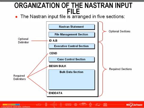
Figure 1: Structure of a MD Nastran input data file.
- the first two sections, Nastran statements and File management section are the only two that are optional and they can end with the optional delimiter
"ID A, B"; - the Executive control section ends with the mandatory delimiter
"CEND"; - the Case control section ends with the mandatory delimiter
"BEGIN BULK"; - the Bulk data section ends with the mandatory delimiter
"ENDDATA".
The Bulk data section is where the geometry model, mesh connectivities, finite element properties, materials, restrictions and loads are described (Those interested in using MD Nastran should note that only the loads referred in the Case control section are considered by MD Nastran).
The Bulk data section
The Bulk data section is composed of entries; each entry contains data distributed in fields. Each line has has 10 fields. The entry name is given in the first field of the first line. The tenth field in each line serves to indicate whether there is an additional line in the entry. An example of this structure can be seen in Figure 2.
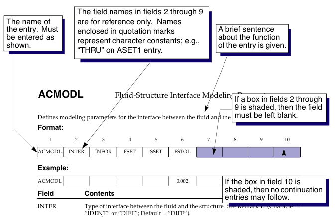
Figure 2: Example of an entry in the Bulk data section.
Data can only be integer, real o string. A string has at most 8 characters. Reals can be written in several ways; for example, 7.0, .7E1, 0.7+1, .70+1, 7.E+0 y 70.-1 are the same number.
MD Nastran has three different formats for data in an entry:
- Free Field Format: data fields are separated by commas;
- Small Field Format: there are 10 contiguous fields, each of them is 8 characters long;
- Large Field Format: there are 10 contiguous fields, each of them is 16 characters long.
2. Features supported by feconv
The valid extension of a MD Nastran input data file to be identified by feconv is the .bdf.
The data format admitted by feconv is the Small Field Format.
In MD Nastran, bi-dimensional models must lie down in the XY plane.
The identification number (ID) of nodes and elements must start in 1 and be consecutive.
Mesh conectivity and node coordinates
The FE types are defined as entries in the Bulk data section, described in Chapter 8 of the MD Nastran 2006 Quick Reference Guide. The name of the entries supported by feconv are CTRIA3, CTRIA6, CQUAD4, CQUAD8, CTETRA, CPENTA and CHEXA. Only CTRIA3 and CTETRA has been tested. In Figure 3 and Figure 4 we show the definition of such entries.
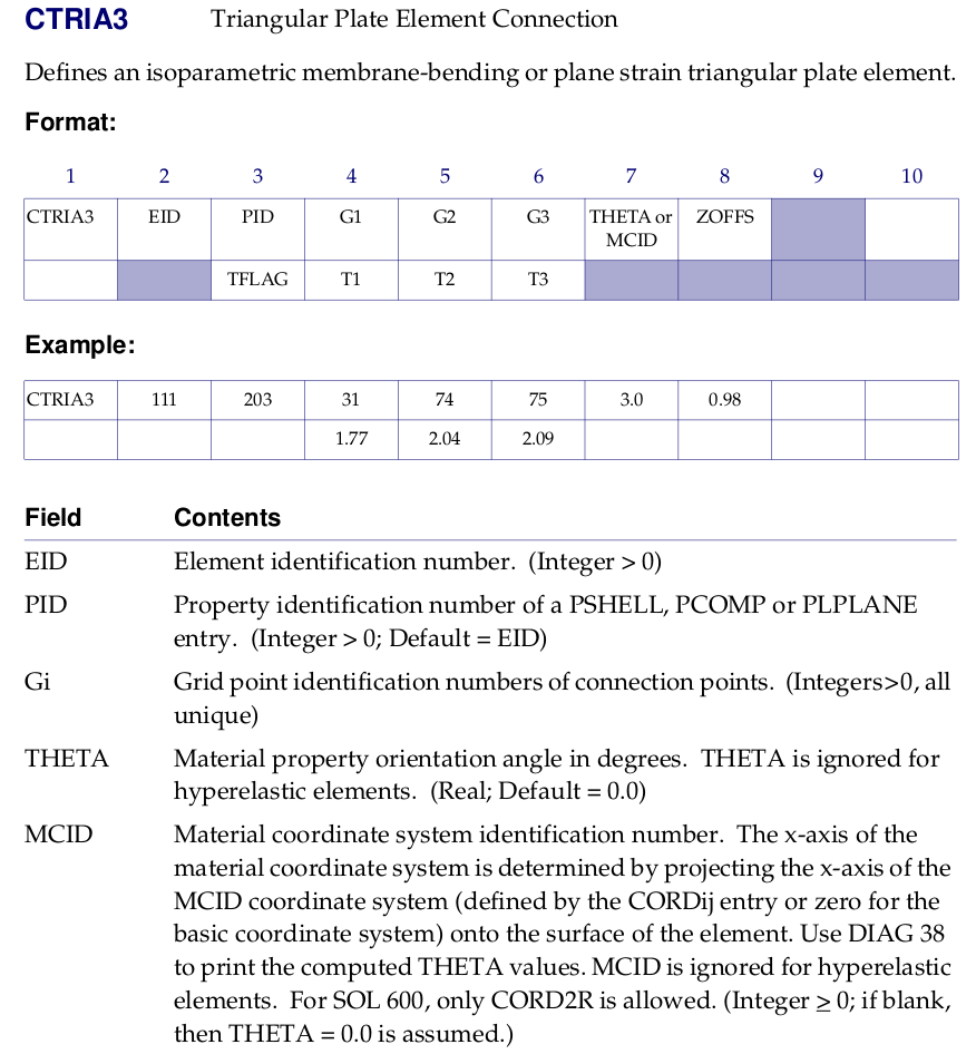
Figure 3: Definition of entry CTRIA3.
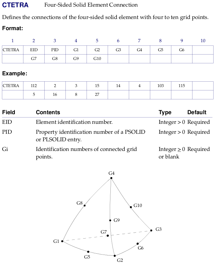
Figure 4: Definition of entry CTETRA.
Those entries store the connectivity of the mesh, that is, the content of variables mm and nn of the MFM format.
For CTRIA3 and CTETRA entries, if the determinant of the matriz of the transformation to the reference element is negative, the last two vertices are exchanged to get a positive determinant.
The node coordinates are defined in the Bulk data section, in the entry named GRID. That gives us the variable z of the MFM format. In Figure 5 we show the definition of such entry.
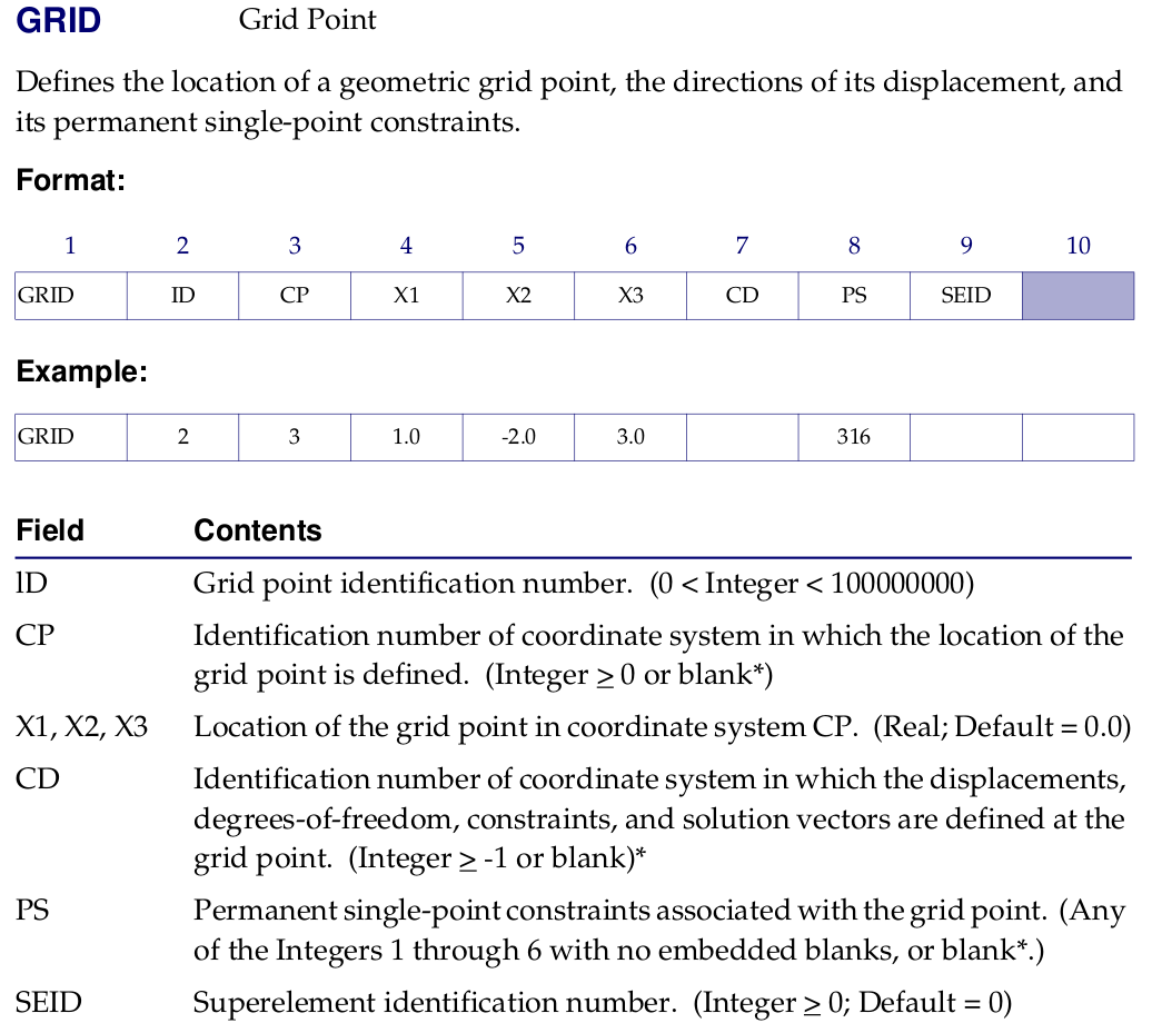
Figure 5: Definition of entry GRID.
The domain references are useful to assign physical properties to subdomains. This information is collected from the PID field of the aforementioned entries. That gives us the variable nsd of the MFM format.
Boundary references
References are useful to apply boundary conditions to the mesh. We distiguish between natural boundary conditions, also called Neumann conditions, and the essential boundary conditions, also called Dirichlet conditions. Dirichlet conditions are imposed as Displacement in MD Nastran and Neumann conditions are imposed as Force. Where both conditions are applied, Dirichlet prevails over Neumann.
Boundary conditions can be imposed on nodes, edges or faces. In the MFM format, those conditions are stored in variables nrv, nra and nrc, respectively. While it is easy to transform face and edge references to node ones, there can be problems doing the inverse conversion; these difficulties are described in section Converting node references to edge and face references.
Dirichlet conditions applied to nodes with SPC entries
Dirichlet conditions applied to nodes are read in feconv from entries SPC and SPC1 in the Bulk data section. The definition of the entry SPC can be seen in Figure 6.
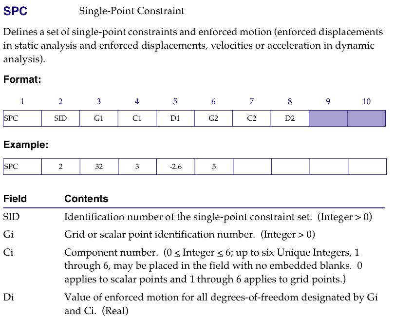
Figure 6: Definition of entry SPC.
Detection of entry SPC was included in feconv because is the default entry used in Hypermesh to set Dirichlet conditions applied to nodes. There are several issues associated with this entry that we describe below:
- In order to know how many different conditions are present in the mesh, we cannot use the field
SIDsince, as far as we know,Hypermeshalways assigns it value 1; we consider instead the value of every displacement, written in theDifield, to group nodes by references. - 6 different restriction degrees can be applied to every node (3 displacements and 3 rotations); every degree is identified in the
Cifield with a number from 1 to 6. - Restrictions for the same node can be saved in different
SPCentries. To manage themHypermeshfollows two rules: - all the
SPCentries for the same condition are contiguous, and - for the same condition, degrees are set in ascending order; for example, if fixed, degree 1 is set before degree 2.
feconvuses the previous rules to deal withSPCentries. As an example, consider oneSPCentry that restrict degrees 1 and 2, and assign them value 8, another one that restrict degrees 3 and 4 with value 10 and a third one for degree 2 with value 7; therefore, we have two reference conditions, the first one restricts degrees 1, 2, 3 and 4 with values 8, 8, 10, 10, respectively; the second one only restricts degree 2 with value 7.- We only know the total number of conditions after all have been read; thus, we use procedure
set_SPCof modulemodule_desplazamientosto store all the conditions due toSPCentries for each node; then, we call procedureassign_SPCto group nodes that belong to the same condition. - In
feconv, when two conditions are assigned to the same node, the one with the biggest reference number will be assigned.
Neumann conditions applied to nodes with FORCE entries
A FORCE entry manages Neumann conditions. The module module_fuerzas deal with these entries in feconv.
Different Neumann conditions are set attending to the value assigned in the Ni field; the SID field is not considered. The definition of the entry FORCE can be seen in Figure 7.
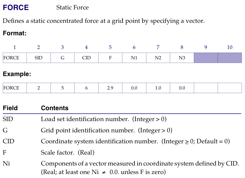
Figure 7: Definition of entry FORCE.
As it was explained for the SPC field, procedure set_FORCE saves all the conditions and procedure assign_FORCE asigns to node the condition with the biggest reference number, provided there is no Dirichlet condition applied to it.
Converting node references to edge and face references
Many solvers require boundary conditions assigned to edges and faces. To do so, we have implemented in feconv two methods:
- to transform the node conditions read in
SPC,SPC1andFORCEentries into edge and face conditions; - to interpret finite elements of smaller dimension as edge and face conditions.
Transforming node references
The transformation of node references to edge references is done in procedure dos; to face references is done in procedures tres and cuatro.
The rules for the transformation are:
- if all the vertices of the entity (edge or face) have the same reference, this one is also applied to the entity;
- if some vertex has no reference assigned (i.e. has reference 0) then no reference is assigned to the entity;
- if the vertices have references of different type, the Neumann condition with the lowest reference number is assigned to the entity;
- otherwise, the reference with the lowest reference number is assigned to the entity.
These rules guarantee that the edges or faces that are in the border between two conditions have assigned Dirichlet over Neumann condition and also the biggest reference number.
You must aware that this rules can fail in some corners. Figure Figure 8 shows a border, as a bold line, between reference conditions 1 and 2. In the finite element of the corner, every vertex has reference 2, making unavoidable that the reference assigned to its edges (and face) will be also 2.
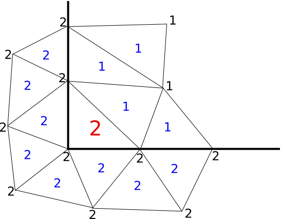
Figure 8: Asignment rules can fail in a corner.
In order to avoid such drawback, we have implemented an alternative way to apply edge and face conditions.
Interpreting FE of smaller dimension
The transformation we will describe here is preferred over the explaind in the previous section, since it does not present the aforementioned drawback. Both types of transformation are applied, but the present one has priority over the first transformation, because it is set after it.
Since the MFM format does not allow hybrid meshes, and this format is the "lingua franca" of feconv, all the finite elements of smaller dimension present in the input file are generally discarded. We have use them to indentify references.
In meshes composed of finite elements defined in CTRIA3 or CTRIA6 entries, every CBEAM entry is interpreted as an edge reference condition; the number associated to that reference is the value stored in the PID field.
In meshes composed of finite elements defined in CTETRA entries, every CTRIA3 entry is interpreted as a face condition; the number associated to that reference is the value stored in the PID field.
