1. Description
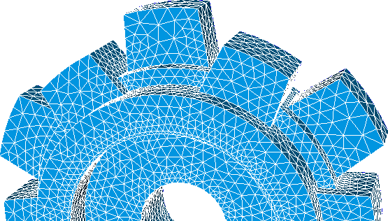
The MSH ASCII file format described at this section is the native mesh format for Gmsh, a three-dimensional finite element mesh generator.
The main features of this format are:
- It can save hybrid meshes, that is, meshes that contain a several types of finite elements.
- The global indexing of nodes and elements do not have to constitute a continuous list.
- The vertex coordinates and field values are defined by floats. Floats can be both of single or double precission.
2. Features supported by feconv
FEconv only support node coordinates and element connectivities when reading. FEconv can also write Gmsh MSH files.
Node coordinates
Coordinates are described inside de Nodes section, the section surrounded by the $Nodes and $EndNodes tags. the First line contains the number of nodes, the rest of lines contains the integer node number and its correspondent 3 float coordinates.
Element connectivities
Connectivities are described inside de Elements section, the section surrounded by the$Elements and $EndElements tags. The First line contains the number of elements, the rest of lines contains several integers with the following meaning:
- 1st integer: element numbering.
- 2nd integer: element type.
- 3rd integer: number of tags.
- 4th integer: physical entity; FEconv use this number to create PMH element groups.
- 5th integer: elementary entity; when saving a Gmsh mesh, FEconv also uses the element numbering as elementary entity.
- Next integers: several node numbers that defines connectivities.
MSH finite element types allowed in feconv
The MSH format describes a lot of different types of finite elements. In the following table you can see the finite elements allowed and its meaning in FEconv.
| MSH descriptor | MSH name | PMH FE types |
|---|---|---|
| 1 | 2-node line | Edge Lagrange P1 |
| 2 | 3-node triangle | Triangle Lagrange P1 |
| 3 | 4-node quadrangle | Quadrilateral Lagrange P1 |
| 4 | 4-node tetrahedron | Tetrahedron Lagrange P1 |
| 5 | 8-node hexahedron | Hexahedron Lagrange P1 |
| 6 | 6-node prism | Wedge Lagrange P1 |
| 8 | 3-node second order line | Edge Lagrange P2 |
| 9 | 6-node second order triangle | Triangle Lagrange P2 |
| 11 | 10-node second order tetrahedron | Tetrahedron Lagrange P2 |
| 15 | 1-node point | Node |
| 16 | 8-node second order quadrangle | Quadrilateral Lagrange P2 |
| 17 | 20-node second order hexahedron | Hexahedron Lagrange P2 |
Local order of nodes
The MSH node ordering respect the following rules:
|
a) 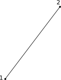
Edge Lagrange P1. |
b) 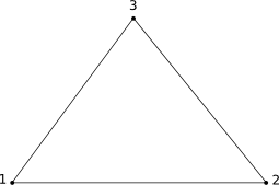
Triangle Lagrange P1. |
c) 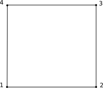
Quadrilateral Lagrange P1. |
|
d) 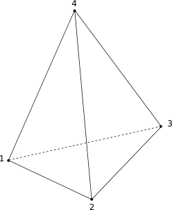
Tetrahedron Lagrange P1. |
e) 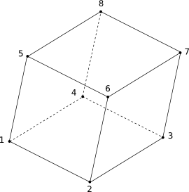
Hexahedron Lagrange P1. |
f) 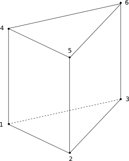
Pentahedron Lagrange P1. |
|
g) 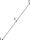
Edge Lagrange P2. |
h) 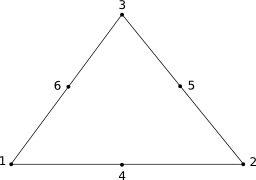
Triangle Lagrange P2. |
i) 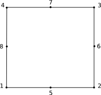
Quadrilateral Lagrange P2. |
|
j) 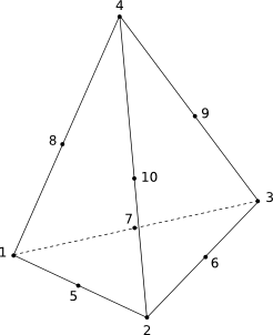
Tetrahedron Lagrange P2. |
k) 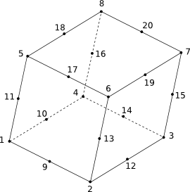
Hexahedron Lagrange P2. |
3. Data structure
Here you can see an example of Gmsh MSH file supported by FEconv:
  $MeshFormat
  2.2 0 8
  $EndMeshFormat
  $Nodes
  6                      six mesh nodes:
  1 0.0 0.0 0.0            node #1: coordinates (0.0, 0.0, 0.0)
  2 1.0 0.0 0.0            node #2: coordinates (1.0, 0.0, 0.0)
  ...
  $EndNodes
  $Elements
  2                      two elements:
  1 3 2 99 2 1 2 3 4       quad #1: type 3, physical 99, elementary 2, nodes 1 2 3 4
  2 3 2 99 2 2 5 6 3       quad #2: type 3, physical 99, elementary 2, nodes 2 5 6 3
  ...
  $EndElements
