
1. Description
The format MFM (Modulef Formatted Mesh) is a simplification of the format NOPO used in Modulef. The file extension for the format MFM is also .mfm.
The main features of this format are:
- It can only save non-hybrid meshes, that is, meshes that contain a single type of finite element.
- The global indexing of vertices and nodes of the mesh can differ when nodes do not coincide with vertices.
- The global indexing of vertices and nodes is saved locally by element in integer arrays.
- Every vertex, edge, face and element in the mesh has a reference number associated to it.
- The reference numbers for vertices, edges, faces and elements are saved locally by element in integer arrays.
- Only the vertex coordinates are saved in a double precision array (node coordinates must be constructed by the solvers).
2. Variables
The meaning of the variables involved in the format MFM is the following:
- nel: total number of elements,
- nnod: total number of nodes (degrees of freedom),
- nver: total number of vertices,
- dim: space dimension,
- lnn: local number of nodes per element,
- lnv: local number of vertices per element,
- lne: local number of edges per element and
- lnf: local number of faces per element.
- nn: integer matrix (lnn × nel) where nn(i,k) is the global index of the i-th node of the k-th element of the mesh.
- mm: integer matrix (lnv × nel) where mm(i,k) is the global index of the i-th vertex of the k-th element of the mesh.
- nrc: integer matrix (lnf × nel) where nrc(i,k) is a reference number associated to the i-th face of the k-th element of the mesh.
- nra: integer matrix (lne × nel) where nra(i,k) is a reference number associated to the i-th edge of the k-th element of the mesh.
- nrv: integer matrix (lnv × nel) where nrv(i,k) is a reference number associated to the i-th vertex of the k-th element of the mesh.
- z: double precision matrix (dim × nver) where z(i,j) is the i-th coordinate of the j-th vertex of the mesh.
- nsd: integer vector (nel) where nsd(k) is a reference number associated to the k-th element of the mesh.
Note that, since lnn, lnv,... are constants, this format does not support an hybrid mesh.
The global indexing of nodes, vertices and elements must start in one and be consecutive.
To define the previous arrays is important to follow a strict rule to locally index the finite element entities. We will see these rules in the next sections.
3. Finite element types
We present a table that summarizes the finite element types supported by feconv:
| Element | FE type | dim | lnn | lnv | lne | lnf | nn≠mm |
|---|---|---|---|---|---|---|---|
| Segment 1D | Lagrange P1 | 1 | 2 | 2 | 0 | 0 | No |
| Segment 2D | Lagrange P1 | 2 | 2 | 2 | 0 | 0 | No |
| Segment 3D | Lagrange P1 | 3 | 2 | 2 | 0 | 0 | No |
| Triangle 2D | Lagrange P1 | 2 | 3 | 3 | 3 | 0 | No |
| Triangle 3D | Lagrange P1 | 3 | 3 | 3 | 3 | 0 | No |
| Triangle 2D | Lagrange P2 | 2 | 3 | 6 | 3 | 0 | Yes |
| Triangle 3D | Lagrange P2 | 3 | 3 | 6 | 3 | 0 | Yes |
| Triangle 2D | Raviart-Thomas (edge) | 2 | 3 | 3 | 3 | 0 | Yes |
| Triangle 3D | Raviart-Thomas (edge) | 3 | 3 | 3 | 3 | 0 | Yes |
| Triangle 2D | P1-bubble | 2 | 3 | 4 | 3 | 0 | Yes |
| Triangle 3D | P1-bubble | 3 | 3 | 4 | 3 | 0 | Yes |
| Tetrahedron 3D | Lagrange P1 | 3 | 4 | 4 | 6 | 4 | No |
| Tetrahedron 3D | Lagrange P2 | 3 | 4 | 10 | 6 | 4 | Yes |
| Tetrahedron 3D | Raviart-Thomas (face) | 3 | 4 | 4 | 6 | 4 | Yes |
| Tetrahedron 3D | Whitney (edge) | 3 | 4 | 6 | 6 | 4 | Yes |
| Tetrahedron 3D | P1-bubble | 3 | 4 | 5 | 6 | 4 | Yes |
Local order of vertices
The local index of vertices in each element must respect the following rules (see Figure 1):
For triangles, the local index of the three vertices satisfies det (v2-v1 | v3-v1) > 0.
For tetrahedra, the local index of the four vertices satisfies det (v2-v1 | v3-v1 | v4-v1) > 0.
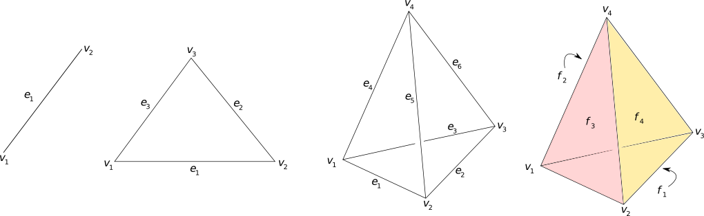
Figure 1: Local order of vertices, edges and faces.
Local index of edges
The local index of edges is determined from the vertex order (see Figure 1). For triangles, the local edge index is shown in the next table:
| Edge | from | to |
|---|---|---|
| e1 | v1 | v2 |
| e2 | v2 | v3 |
| e3 | v3 | v1 |
For tetrahedra, the local edge index is shown in the next table:
| Edge | from | to |
|---|---|---|
| e1 | v1 | v2 |
| e2 | v2 | v3 |
| e3 | v3 | v1 |
| e4 | v1 | v4 |
| e5 | v2 | v4 |
| e6 | v3 | v4 |
Local order of faces
The local index of faces is determined from the vertex order (see Figure 1). For tetrahedra, the local face index is shown in the next table:
| Face | contains | ||
|---|---|---|---|
| f1 | v1 | v3 | v2 |
| f2 | v1 | v4 | v3 |
| f3 | v1 | v2 | v4 |
| f4 | v2 | v3 | v4 |
The local index of nodes (degrees of freedom) also depends on the finite element type. Nodes can be located on vertices, edges, faces and barycenter (here denoted by b). For segments, the local node index is shown in the next table:
| FE type | Nodes |
|---|---|
| Lagrange P1 | v1, v2 |
| Lagrange P2 | v1, v2, e1 |
For triangles, the local node index is shown in the next table.
| FE type | Nodes |
|---|---|
| Lagrange P1 | v1, v2, v3 |
| Lagrange P2 | v1, v2, v3, e1, e2, e3 |
| Raviart-Thomas (edge) | e1, e2, e3 |
| P1-bubble | v1, v2, v3, b |
For tetrahedra, the local node index is shown in the next table:
| FE type | Nodes |
|---|---|
| Lagrange P1 | v1, v2, v3, v4 |
| Lagrange P2 | v1, v2, v3, v4, e1, e2, e3, e4, e5, e6 |
| Raviart-Thomas (face) | f1, f2, f3, f4 |
| Whitney (edge) | e1, e2, e3, e4, e5, e6 |
| P1-bubble | v1, v2, v3, v4, b |
The last column indicated whether the global index of nodes is different from the one for vertices. They only coincide for Lagrange P1 elements; we will see that for those elements nn is not written.