
1. Description
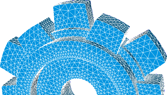
The PF3 file format is used by the software Flux, for electromagnetic and thermal simulations, developed by Cedrat.
The main features of this format are:
- It can store hybrid meshes, that is, meshes that contain a several types of finite elements.
- It can store coordinates, connectivities, references and fields at nodes.
- The global indexing of nodes, vertices and elements must start in one and be consecutive.
- The vertex coordinates and field data are given by single precission floats.
Feconv uses with double precission floats to work with coordinates and fields. For proper reading of PF3 meshes you must use the options -t , to set the tolerance of the mesh, and -r soft, to check the node ordering for the first element and assume it for all the elements.
2. Features supported by feconv
PF3 contains plain text for most of the information. It can contains binary data to assign names to regions. FEconv can only read the plain text and discards the binary data.
Finite element types
The PF3 format describes a lot of different types of finite elements. In the following table you can see the finite elements allowed by FEconv and its description in PMH.
PF3 descriptors corresponds, respectively, with the 2nd, 3rd and 7th number of the 12 numbers of the element description.
| PF3 descriptor | PF3 name | FE type |
|---|---|---|
| (2 , 2, 3) | Line first order | Edge Lagrange P1 |
| (2 , 3, 4) | Line second order | Edge Lagrange P2 |
| (3 , 7, 5) | Triangle first order | Triangle Lagrange P1 |
| (3 , 7, 6) | Triangle second order | Triangle Lagrange P2 |
| (4 , 202, 7) | Rectangle first order | Quadrilateral Lagrange P1 |
| (4 , 303, 8) | Rectangle second order | Quadrilateral Lagrange P2 |
| (5 , 4, 10) | Tetrahedron first order | Tetrahedron Lagrange P1 |
| (5 , 15, 11) | Tetrahedron second order | Tetrahedron Lagrange P2 |
| (6 , 207, 12) | Prism first order | Wedge Lagrange P1 |
| (7 , 2202, 15) | Hexahedron first order | Hexahedron Lagrange P1 |
| (7 , 3303, 16) | Hexahedron second order | Hexahedron Lagrange P2 |
Local order of nodes
The ordering of the nodes has been deduced empirically. We have observed that the local order of nodes in each element respect the following rules:
|
a) 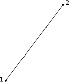
Edge Lagrange P1. |
b) 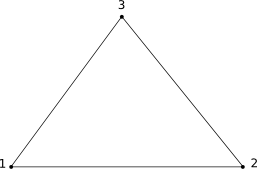
Triangle Lagrange P1. |
c) 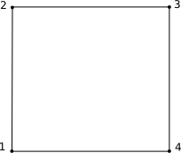
Quadrilateral Lagrange P1. |
|
d) 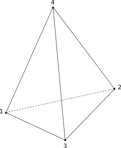
Tetrahedron Lagrange P1. |
e) 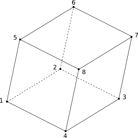
Hexahedron Lagrange P1. |
f) 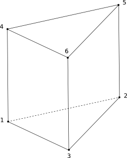
Pentahedron Lagrange P1. |
|
g) 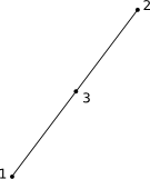
Edge Lagrange P2. |
h) 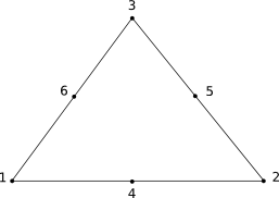
Triangle Lagrange P2. |
i) 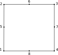
Quadrilateral Lagrange P2. |
|
j) 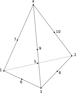
Tetrahedron Lagrange P2. |
k) 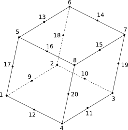
Hexahedron Lagrange P2. |
3. File structure
The structure of the PF3 mesh files starts with a header, followed by the region names, elements description, coordinates and optionally a single field.
Header
The PF3 header describes, among others, the space dimension, number of points, number of elements and number of regions as follows:
 Fichier cree par F3DXPE 1.0. Date: 18/01/13 16:49:20
       3           NOMBRE DE DIMENSIONS DU DECOUPAGE
      78           NOMBRE  D'ELEMENTS
      78           NOMBRE  D'ELEMENTS VOLUMIQUES
       0           NOMBRE  D'ELEMENTS SURFACIQUES
       0           NOMBRE  D'ELEMENTS LINEIQUES
       0           NOMBRE  D'ELEMENTS PONCTUELS
       0           NOMBRE DE MACRO-ELEMENTS
     195           NOMBRE DE POINTS
       1           NOMBRE DE REGIONS
       1           NOMBRE DE REGIONS VOLUMIQUES
       0           NOMBRE DE REGIONS SURFACIQUES
       0           NOMBRE DE REGIONS LINEIQUES
       0           NOMBRE DE REGIONS PONCTUELLES
       0           NOMBRE DE REGIONS MACRO-ELEMENTAIRES
      20           NOMBRE DE NOEUDS DANS 1 ELEMENT (MAX)
      20           NOMBRE DE POINTS D'INTEGRATION / ELEMENT (MAX)
Element description
The element description consists of twelve integers, following we describe the most significant of them:
- The 1st number give us the element numbering.
- The 2nd, 3rd and 7th describes the element shape and order.
- The 4th number represents the number of region to which the element belongs.
- The 5th means the kind of topology; 4 for 3D elements, 3 for 2D elements and 2 for 1D elements.
- The 8th number give us the number of nodes of the element.
Here is an example showing the connectivities of a Lagrange P1 tetrahedral mesh:
 DESCRIPTEUR DE TOPOLOGIE DES ELEMENTS
              1        5        4        1        4        0       10        4        0        0        0        0
             33       10       48       34
              2        5        4        1        4        0       10        4        0        0        0        0
             32       76       49       61
              3        5        4        1        4        0       10        4        0        0        0        0
              4       38       27       22
              ...
Node coordinates
The coordinates of the nodes are numbered consecutively starting at one. Note that by default PF3 work with single precission floats to express the values of the coordinates.
Look at the following example:
 COORDONNEES DES NOEUDS
       1   0.1207407E-01  0.3235238E-02   0.000000
       2   0.1207407E-01 -0.3235238E-02   0.000000
       3   0.2076741E-01  0.5564609E-02   0.000000
       4   0.2076741E-01 -0.5564609E-02   0.000000
       5   0.1207407E-01  0.3235238E-02  0.6000000E-02
       6   0.2076741E-01  0.5564609E-02  0.6000000E-02
       7   0.2076741E-01 -0.5564609E-02  0.6000000E-02
       8   0.1207407E-01 -0.3235238E-02  0.6000000E-02
       ...
 ==== DECOUPAGE  TERMINE
Field
Optionally, PF3 files can contain a single field. This consists of a field name followed by the number of components and points and then a list of values. See the following example:
 Table of the values of     TCelsius    (Local values on the nodes of the region PIECE)
       1       195 (Nb of components, nb of points)

          24.01930
          20.15225
          28.82810
          164.0529
          163.7079
       ...