
1. Description
The format PMH (Piecewise Mesh) is based on the format MFM. The file extension for the format PMH is also .pmh.
The main features of this format are:
- It can store piecewise meshes, each piece identify independent parts of a whole.
- It can store hybrid meshes, that is, meshes that contain several types of finite elements.
- It can store parameter dependant fields at nodes or on elements
- The global indexing of vertices and nodes of the mesh can differ when nodes do not coincide with vertices.
- The global indexing of vertices and nodes is saved locally by element in integer arrays.
- Every vertex, edge, face and element in the mesh has a reference number associated to it.
- The reference numbers for vertices, edges, faces and elements are saved locally by element in integer arrays.
- Only the vertex coordinates are saved in a double precision array. Lagrange P2 node coordinates are calculated at the midpoints of the line joining two vertices.
- Correct local ordering of nodes at elements ensures positive jacobian in groups of elements with maximal topological dimension.
2. Finite element types
The meaning of the variables involved in the description of each finite element type in format PMH are the following:
- dim: space dimension,
- tdim: topological dimension,
- lnn: local number of nodes per element,
- lnv: local number of vertices per element,
- lne: local number of edges per element and
- lnf: local number of faces per element.
We present a table that summarizes the finite element types supported by feconv:
| Geometric entity | FE type | tdim | lnn | lnv | lne | lnf | nn≠mm |
|---|---|---|---|---|---|---|---|
| Edge | Lagrange P1 | 1 | 2 | 2 | 0 | 0 | No |
| Edge | Lagrange P2 | 1 | 3 | 2 | 0 | 0 | Yes |
| Triangle | Lagrange P1 | 2 | 3 | 3 | 3 | 0 | No |
| Triangle | Lagrange P2 | 2 | 6 | 3 | 3 | 0 | Yes |
| Triangle | Raviart-Thomas (edge) | 2 | 3 | 3 | 3 | 0 | Yes |
| Quadrangle | Lagrange P1 | 2 | 4 | 4 | 4 | 0 | No |
| Quadrangle | Lagrange P2 | 2 | 8 | 4 | 4 | 0 | Yes |
| Tetrahedron | Lagrange P1 | 3 | 4 | 4 | 6 | 4 | No |
| Tetrahedron | Lagrange P2 | 3 | 4 | 10 | 6 | 4 | Yes |
| Tetrahedron | Raviart-Thomas (face) | 3 | 4 | 4 | 6 | 4 | Yes |
| Tetrahedron | Whitney (edge) | 3 | 4 | 6 | 6 | 4 | Yes |
| Hexahedron | Lagrange P1 | 3 | 8 | 8 | 12 | 6 | No |
| Hexahedron | Lagrange P2 | 3 | 20 | 8 | 12 | 6 | Yes |
| Pentahedron | Lagrange P1 | 3 | 6 | 6 | 9 | 5 | No |
The last column indicated whether the global index of nodes is different from the one for vertices. They only coincide for Lagrange P1 elements; we will see that for those elements nn is not stored.
Local index of vertices
The local index of nodes in each element are shown in Figure 1.
|
a) 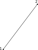
Edge Lagrange P1. |
b) 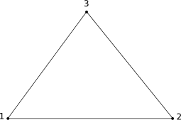
Triangle Lagrange P1. |
c) 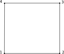
Quadrilateral Lagrange P1. |
|
d) 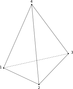
Tetrahedron Lagrange P1. |
e) 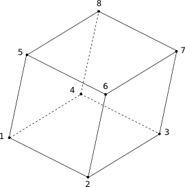
Hexahedron Lagrange P1. |
f) 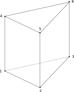
Pentahedron Lagrange P1. |
|
g) 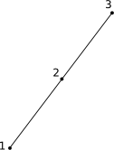
Edge Lagrange P2. |
h) 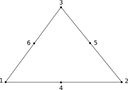
Triangle Lagrange P2. |
i) 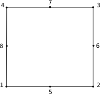
Quadrilateral Lagrange P2. |
|
j) 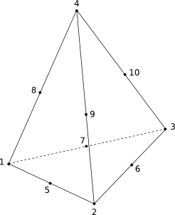
Tetrahedron Lagrange P2. |
k) 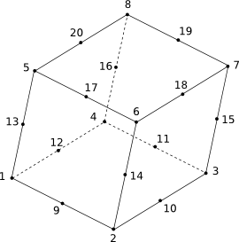
Hexahedron Lagrange P2. |
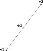
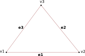
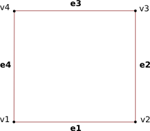
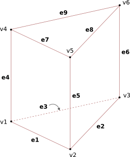
Local index of edges
The local index of edges is determined from the vertex order. See Figure 2.
|
||
|
||
|
||
|
||
|
||
|
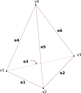

Local index of faces
The local index of faces is determined from the vertex order. See Figure 3.
|
a) 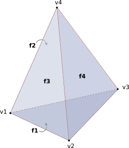
Tetrahedron. |
|
||||||||||||||||||||||||||||||||||||||||
|
b) 
Hexahedron. |
|
||||||||||||||||||||||||||||||||||||||||
|
c) 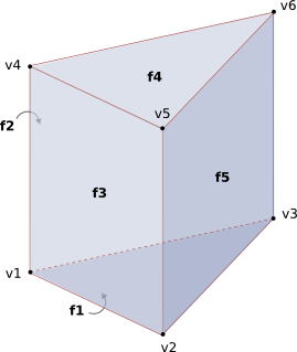
Pentahedron. |
|
||||||||||||||||||||||||||||||||||||||||
3. Implementation
Variables
The meaning of the variables involved in the format PMH are the following:
- pc: vector of pieces that compose the mesh,
- ztol: mesh coordinates tolerance,
- z: double precision matrix (dim × nver) where z(i,j) is the i-th coordinate of the j-th vertex of the mesh.
- el: vector of element groups,
- fi: vector of fields associated to nodes or elements,
- nel: total number of elements,
- nnod: total number of nodes (degrees of freedom),
- nver: total number of vertices,
- ref: integer vector (nel) where ref(k) is a reference number associated to the k-th entity of the element group.
The global indexing of nodes, vertices and elements must start in one and be consecutive.
To define the previous arrays is important to follow a strict rule to locally index the finite element entities. We will see these rules in the next sections.
Data structure
The structure of data storing for PMH meshes and fields in Fortran
        type field
           character(maxpath)        :: name       !Field name
           real(real64), allocatable :: param(:)   !Parameter values
           real(real64), allocatable :: val(:,:,:) !Field value for each parameter
        end type


        type elgroup
           integer                    :: nel  = 0 !Total number of elements
           integer                    :: type = 0 !Element type (one of those defined in module_fe_database_pmh)
           integer,     allocatable   :: nn(:,:)  !Global numbering of nodes
           integer,     allocatable   :: mm(:,:)  !Global numbering of vertices
           integer,     allocatable   :: ref(:)   !Reference numbering
           type(field), allocatable   :: fi(:)    Fields on elements
        end type


        type piece
           integer                    :: nnod = 0 !Total number of nodes
           integer                    :: nver = 0 !Total number of vertices
           integer                    :: dim  = 0 !Space dimension of the node/vertex coordinates
           real(real64),  allocatable :: z(:,:)   !Vertex coordinates
           type(elgroup), allocatable :: el(:)    !Element groups
           type(field),   allocatable :: fi(:)    !Fields at nodes
        end type


        type pmh_mesh
           type(piece), allocatable   :: pc(:) !Pieces that compose the mesh
           real(real64)               :: ztol = epsilon(0._real64) !Mesh tolerance
        end type