
1. Description
The Universal File formats were originally developed by the Structural Dynamics Research Corporation (SDRC) in the late 1960s and early 1970s to facilitate computer aided engineering (CAE). This format is described in the web page of the Structural Dynamics Research Lab at the University of Cincinnati (UC-SDRL). The file extension for the format UNV is also .unv.
The main features of this format are:
- It can save hybrid meshes, that is, meshes that contain a several types of finite elements.
- The global indexing of nodes, edges, faces and elements are defined by integers.
- The vertex coordinates and field values are defined by floats of double precision.
- Each set of coordinates, connectivities, references and fields are stored in its own dataset.
- The node datasets contains the node number and their coordinates among other information
- The element datasets contains the element number, element descriptor, number of nodes and their connectivities among other information
- The group datasets contains the group number, group name and a set of entities with their tags and entity types among other information
- The field datasets contains the field descriptors and a set of entities with their values and entity numbers among other information
2. Features supported by feconv
The identification number (ID) of nodes and elements must start in 1 and be consecutive.
Node datasets
The node dataset contains the node number and their coordinates among other information. Feconv supports the datasets 2411 and 781 for reading node definition and uses the dataset 2411 for writing node data.
Element dataset
The element datasets contains the element number, element descriptor, number of nodes and their connectivities among other information. Feconv supports the dataset 2412 for reading and writing element definition.
UNV finite element types allowed in feconv
The UNV format describes a lot of different types of finite elements. In the following table you can see the finite elements allowed and its meaning in FEconv.
| UNV descriptor | UNV name | FE type |
|---|---|---|
| 11 | Rod | Edge Lagrange P1 |
| 21 | Linear Beam | Edge Lagrange P1 |
| 22 | Tapered Beam | Edge Lagrange P2 |
| 24 | Parabolic Beam | Edge Lagrange P2 |
| 41 | Plane Stress Linear Triangle | Triangle Lagrange P1 |
| 42 | Plane Stress Parabolic Triangle | Triangle Lagrange P2 |
| 44 | Plane Stress Linear Quadrilateral | Quadrilateral Lagrange P1 |
| 45 | Plane Stress Parabolic Quadrilateral | Quadrilateral Lagrange P2 |
| 81 | Axisymetric Solid Linear Triangle | Triangle Lagrange P1 |
| 82 | Axisymetric Solid Parabolic Triangle | Triangle Lagrange P2 |
| 84 | Axisymetric Solid Linear Quadrilateral | Quadrilateral Lagrange P1 |
| 85 | Axisymetric Solid Parabolic Quadrilateral | Quadrilateral Lagrange P2 |
| 91 | Thin Shell Linear Triangle | Triangle Lagrange P1 |
| 92 | Thin Shell Parabolic Triangle | Triangle Lagrange P2 |
| 94 | Thin Shell Linear Quadrilateral | Quadrilateral Lagrange P1 |
| 95 | Thin Shell Parabolic Quadrilateral | Quadrilateral Lagrange P2 |
| 111 | Solid Linear Tetrahedron | Tetrahedron Lagrange P1 |
| 112 | Solid Linear Wedge | Wedge Lagrange P1 |
| 115 | Solid Linear Brick | Hexahedron Lagrange P1 |
| 116 | Solid Parabolic Brick | Hexahedron Lagrange P2 |
| 118 | Solid Parabolic Tetrahedron | Tetrahedron Lagrange P2 |
| 122 | Rigid Element | Quadrilateral Lagrange P1 |
Local order of nodes
There is no a formal specification about node ordering of UNV finite elements, it has been checked that the node order used in some software like Salome, Code Aster or Ansys Fluent introduces the nodes sandwiched between the vertices.
Salome can create pure isoparametric elements, it means Lagrange P2 elements with curved sides. Feconv only works with elements that its nodes lie on the midpoint of the straight line that connects two vertices; note that feconv check de midnodes to build connectivities properly. The way to read this kind of elements in feconv is to use the -r sandwich option.
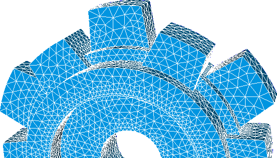
The local order of nodes in each element respect the following rules:
|
a) 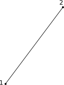
Edge Lagrange P1. |
b) 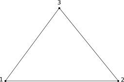
Triangle Lagrange P1. |
c) 
Quadrilateral Lagrange P1. |
|
d) 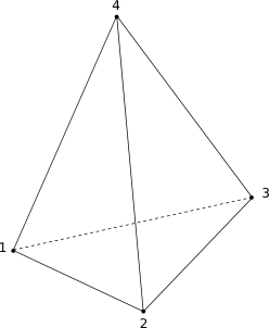
Tetrahedron Lagrange P1. |
e) 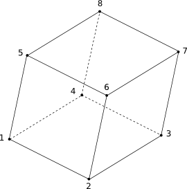
Hexahedron Lagrange P1. |
f) 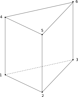
Pentahedron Lagrange P1. |
|
g) 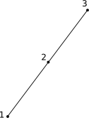
Edge Lagrange P2. |
h) 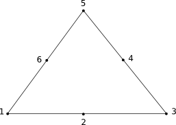
Triangle Lagrange P2. |
i) 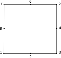
Quadrilateral Lagrange P2. |
|
j) 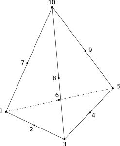
Tetrahedron Lagrange P2. |
k) 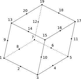
Hexahedron Lagrange P2. |
Group datasets
Groups behave as references, and are useful to apply boundary conditions, materials ans sources to the mesh. Groups can contain nodes, edges, faces or elements.
The group datasets contains the group number, group name and a set of entities with their tags and entity types among other information. Feconv supports the dataset 2467, 2477,2452, 2435, 2432 and 2430 for reading groups definition. Feconv uses then dataset 2467 for writing UNV groups.
Field datasets
The field datasets contain the field descriptors and a set of entities with their values and entity numbers among other information. Feconv supports the dataset 2414, 55, 56 and 57 for reading field definition. Feconv uses the dataset 2414 for writing UNV fields.
There may be scalar and vector fields, vector fields can have 3 componentes, 6 components for symmetric global tensors or 9 componentes for general tensors.
The field values can be located at nodes, on elements or at nodes on elements. Feconv only allows fields at nodes and on elements; data at nodes on elements will be processed to calculate the average of all node values and store it on the element barycenter.
Field identification, in addition to its name, is given by the information of the problem solved. Code Aster defines the relationship between these information and the field name through lire_resu function, you can use -ca option to read/write Code Aster UNV files.